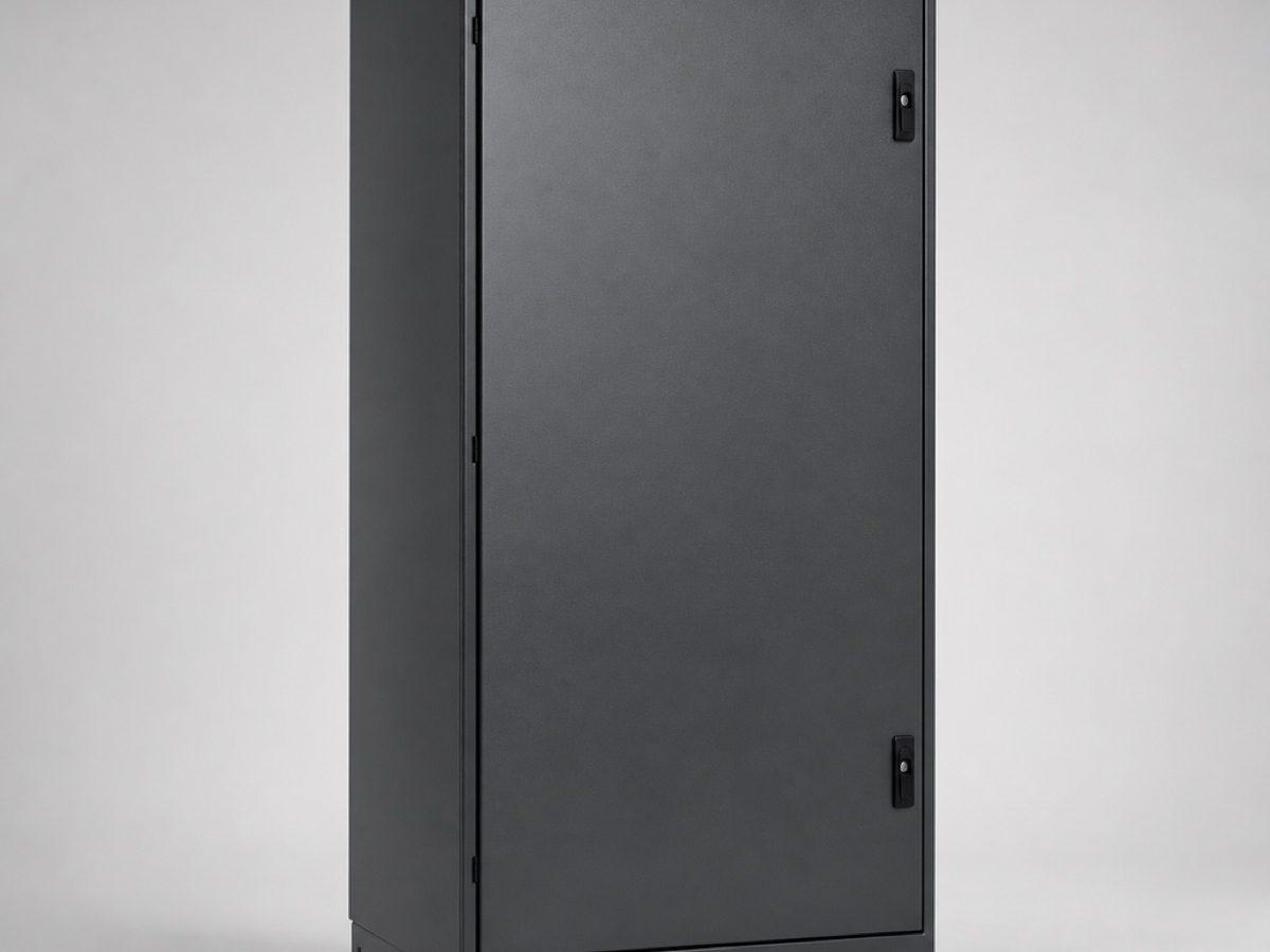
The automatic transfer switch is usually the last line on a standby specification and the first thing blamed when the changeover does not behave. Two things about it are routinely got wrong on drawings issued for tender.
It is rated for the mains, not the set
The transfer switch sits in the incoming supply. For almost all of its life it carries the full building load from the utility, and it only carries generator load during an outage. Its continuous current rating therefore has to match the incoming protective device, not the generator’s output current.
The second rating that matters is short-circuit withstand. The prospective fault level at the point of installation comes from the utility transformer, and it is far higher than anything the generator can contribute. A switch chosen against the generator fault level will not survive a fault on the mains side. Ask for the Icw and Icm figures and check them against the fault level study, not against the set.
The third is utilisation category. Transfer switching equipment is classified as class PC, which is designed to make and withstand short-circuit currents but not to break them, or class CB, which incorporates the protective devices. Which one is right depends on the discrimination arrangement upstream.
The transfer time question
People ask how fast the transfer is, and the answer they get is the operating time of the mechanism, often quoted as a fraction of a second. That number is real and it is almost never the number the load experiences.
The interval the load sees runs from the moment the mains fails to the moment the generator contact closes, and it is the sum of four things: the start delay, which stops a momentary dip from starting the set; the cranking and run-up time; the delay while the controller waits for voltage and frequency to be stable and in tolerance; and the mechanism transfer time itself. For a healthy diesel set on a well-configured panel, ten to fifteen seconds is a normal total. The mechanism is a small fraction of it.
That total is what determines whether the connected equipment rides through. Anything that cannot tolerate ten seconds of darkness, which means IT load, medical imaging, process control and most life-safety lighting, needs a UPS or a central battery system in front of it. The generator restores the supply; it does not make it continuous.
The four delays worth setting properly
Start delay. Long enough that a one-second dip does not start the set, short enough that a real outage is not wasted waiting. Typically one to three seconds.
Transfer delay. After the set reaches stable voltage and frequency. Setting it too short transfers onto a set that is still recovering.
Return delay. After the mains returns, before the load goes back. This exists because the mains often returns unstable, and a load that bounces back and forth is worse than one that waits. Several minutes is usual.
Cool-down run. After the load is transferred back, the set runs off load so the turbocharger and the coolant temperature come down under control. Shutting a hot turbo down immediately shortens its life.
All four are adjustable and all four should be set at commissioning against the actual installation. Factory defaults are a starting point and nothing more.
Three pole or four
Four-pole switching breaks the neutral as well as the phases, which keeps the mains and generator systems separately earthed and avoids circulating neutral currents between two earth reference points. Three-pole switching keeps a solid neutral throughout. Which is correct depends on the earthing arrangement of the installation and on the protection scheme, and it is a decision for the electrical designer rather than a catalogue option. [Client to confirm the earthing arrangement and discrimination study for their installations.]