Ultrafiltration

Clearflow UF-PV 600
Outside-in PVDF ultrafiltration rack on fixed-flux control for high-turbidity feeds.
- 60 m³/hPermeate
- 99.99 %Rejection
- 93 %Recovery
- 0.14 kWh/m³Specific energy
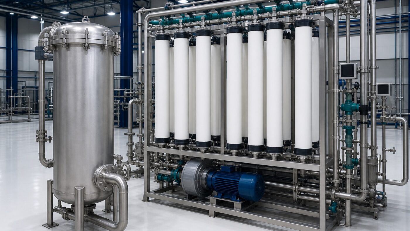
Compact hollow-fibre UF skid delivering SDI15 below 3 to a downstream RO train.
Eight PVDF modules on a stainless frame with an air-scour blower and an automatic backwash sequence. Its only job is to hand a stable SDI to whatever sits downstream — and it does that whether the raw water is 2 NTU or 50 NTU.
The Clearflow UF-HC 150 is a standard Clearflow configuration rated at 15 m³/h of permeate at 92 % system recovery, which is 360 m³ over a continuous day. The published envelope assumes 25 °C, a clean membrane and the design feed analysis; every project is re-projected against the water you actually have before a price is issued.
The array is arranged as single rack, 8 modules in parallel. Element type is PVDF outside-in hollow fibre module, 55 m² each, running on hydrophilic PVDF, 0.03 µm nominal pore size. Design flux is held at 34.1 LMH so the concentrate velocity through the last element stays inside the manufacturer envelope at design recovery — the single most reliable predictor of how long the membranes will last.
| Parameter | Design value | Note |
|---|---|---|
| Feed pressure | 1.8 bar | At design feed TDS and 25 °C |
| Trans-membrane differential | 0.55 bar | Clean; change-out trigger at twice this value |
| Feed temperature | 5–40 °C | Output falls roughly 3 % per °C below 25 °C |
| Continuous pH | 2.0–11.0 | Wider band tolerated during cleaning |
| Free chlorine | Max 200.00 mg/L | Continuous exposure limit at the membrane face |
| Concentrate flow | 1.3 m³/h | At design recovery |
Chemically enhanced backwash every 24 h plus monthly CIP, 300 L. Control is by Industrial PLC with fixed-flux, variable-TMP control loop. The wetted specification is 316L manifolds, uPVC low-pressure lines, PVDF module bodies. Pressurisation is by horizontal feed pump plus dedicated backwash pump, both 316L; not applicable to a low-pressure barrier.
| Permeate capacity | 15 m³/h |
|---|---|
| Daily output at 24 h | 360 m³/d |
| System recovery | 92 % |
| Design feed flow | 16.3 m³/h |
| Concentrate flow | 1.3 m³/h |
| Nominal rejection | 99.99 % |
|---|---|
| Typical permeate TDS | 2,955 mg/L |
| Design flux | 34.1 LMH |
| Feed pressure | 1.8 bar |
| Trans-membrane ΔP | 0.55 bar |
| Specific energy | 0.12 kWh/m³ |
| Max feed TDS | 3,000 mg/L |
|---|---|
| Min design feed TDS | 0 mg/L |
| Max feed SDI15 | 20.0 |
| Max feed turbidity | 50.00 NTU |
| Min feed temperature | 5 °C |
| Max feed temperature | 40 °C |
| Min continuous pH | 2.0 |
| Max continuous pH | 11.0 |
| Max free chlorine | 200.00 mg/L |
| Membrane elements | 8 pcs |
|---|---|
| Pressure vessels | 8 pcs |
| Elements per vessel | 1 pcs |
| Stage 1 vessels | 8 pcs |
| Stage 2 vessels | 0 pcs |
| Array configuration | Single rack, 8 modules in parallel |
| Element type | PVDF outside-in hollow fibre module, 55 m² each |
| Membrane chemistry | Hydrophilic PVDF, 0.03 µm nominal pore size |
| Active membrane area | 440 m² |
| Pressure pump | Horizontal feed pump plus dedicated backwash pump, both 316L |
|---|---|
| Energy recovery | Not applicable to a low-pressure barrier |
| Wetted materials | 316L manifolds, uPVC low-pressure lines, PVDF module bodies |
| Control system | Industrial PLC with fixed-flux, variable-TMP control loop |
| Cleaning regime | Chemically enhanced backwash every 24 h plus monthly CIP, 300 L |
| Skid footprint L×W×H | 3.2 × 1.6 × 2.4 m |
| Dry shipping weight | 1,250 kg |
| Installed motor load | 7.5 kW |
| Indicative lead time | 8–10 weeks ex works |
Send us the feed analysis and duty flow and we will re-project this array against your water.
Outside-in PVDF ultrafiltration rack on fixed-flux control for high-turbidity feeds.
Send us the duty flow, the feed water analysis and the permeate specification you have to hit. Our process desk replies within one working day.