Coolant Distribution
KX-CDU L1300
Liquid-to-Liquid Coolant Distribution Unit
Our largest floor-standing CDU: 1,300 kW of isolated heat transfer with N+1 pumps and ±0.5 K secondary control.
- Rated capacity
- 1,300 kW
- Per rack
- 65 kW
- Nominal Delta-T
- 10 K
- Nominal flow
- 1,866 L/min
- Supply water
- W17 – W45 (17 – 45 °C)
- Max pressure
- 6.0 bar
- Partial PUE
- 1.06
- Working fluid
- Treated water or PG25 on both circuits

The KX-CDU L1300 is the unit we put at the head of a full row of high-density racks. It transfers up to 1,300 kW between the facility water system and the technology cooling loop through a brazed stainless plate exchanger, which means the water your servers see is never the water your building made.
Why isolation matters
Facility water carries whatever the building gives it: particulate from steel pipework, variable chemistry, and the occasional maintenance event. Cold plate microchannels are 0.3 mm wide. Putting one directly on the other is a fouling incident waiting for a date. The L1300 keeps the two circuits mechanically separate and lets you run the technology side on a chemistry you actually control.
Redundancy that survives a service call
Two centrifugal pumps share the load and either one will carry the full rated duty on its own. Both are hot-swappable from the front without breaking the loop, so a pump replacement is a maintenance task rather than an outage. Controllers, sensors and power feeds are duplicated on the same principle.
Control and reporting
Secondary supply temperature is held to ±0.5 K across the turndown range, which is what keeps the die temperature flat when a training job steps the rack load by tens of kilowatts in a second. Every sensor on the unit is exposed over Modbus TCP, BACnet/IP and SNMP v3, so the loop shows up in your DCIM as data rather than as an alarm contact.
Before it ships
Every L1300 runs on our test rig at rated flow and pressure. You receive the measured pump curve, the approach temperature at duty and the leak test record with the unit. If you want a witnessed factory acceptance test, we will schedule one.
Technical data
Full specification
Values are at nominal duty. Ask us for the full performance map if you are working outside these conditions.
| Rated capacity | 1,300 kW |
|---|---|
| Configuration | Liquid-to-liquid, isolated |
| Primary supply temperature | 17 – 45 °C |
| Nominal Delta-T | 10 K |
| Secondary flow rate | 1,866 L/min |
| Secondary temperature stability | ±0.5 K |
| Maximum working pressure | 6 bar |
| Pump configuration | N+1 hot-swap centrifugal |
| Heat exchanger | Brazed stainless steel plate |
| Filtration | 50 µm inline, serviceable under load |
| Electrical supply | 400 V 3-phase, 50/60 Hz, dual feed |
| Communications | Modbus TCP, BACnet/IP, SNMP v3 |
| Footprint (W × D × H) | 900 × 1,200 × 2,100 mm |
| Dry weight | 820 kg |
| Partial PUE contribution | 1.06 |
Module 05 — Flow envelope
Delta-T against required flow
This unit rejects 1,300 kW. Widening the temperature difference across the loop cuts the volume of water you have to move — and pump power falls with roughly the cube of flow.
- Required flow
- 1,866 L/min
- Return temperature
- 40.0 °C at W30 supply
- Relative pump power
- 100 % of nominal
Water at 4.18 kJ/kg·K, density taken as 1 kg/L. Pump power index scales with the cube of the flow ratio against this unit’s nominal 10.0 K design point.
Related
Others in this range
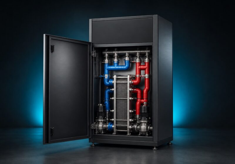
KX-CDU L600
Mid-Range Liquid-to-Liquid CDU
600 kW in a single-row footprint — the right size for a first liquid cooling pod without over-buying capacity.
- Capacity
- 600 kW
- Per rack
- 30 kW
- Delta-T
- 10 K
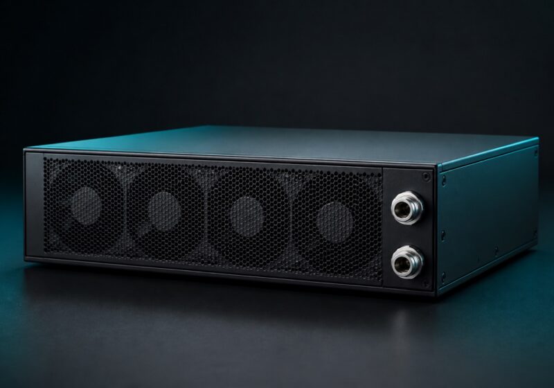
KX-CDU A120
In-Rack Liquid-to-Air CDU
A self-contained 4U CDU that rejects to room air — liquid cooling for sites with no facility water at all.
- Capacity
- 120 kW
- Per rack
- 120 kW
- Delta-T
- 12 K