KX-CDU L1300
Liquid-to-Liquid Coolant Distribution Unit
Our largest floor-standing CDU: 1,300 kW of isolated heat transfer with N+1 pumps and ±0.5 K secondary control.
- Capacity
- 1,300 kW
- Per rack
- 65 kW
- Delta-T
- 10 K

Data Centre Liquid Cooling
Kelvinix engineers coolant distribution units, direct-to-chip cold plates, rear door heat exchangers and immersion systems for racks running from 30 kW to 200 kW — validated, instrumented and delivered as one thermal loop.
The thermal wall
A single accelerator package now dissipates more heat than an entire rack did fifteen years ago. Fans get louder, inlet temperatures creep up, and throttling quietly eats the performance you paid for.
Water carries roughly 3,000 times more heat per unit volume than air. No fan curve closes that gap.
Server fans alone can consume 8 – 15 % of IT power in a dense air-cooled rack. Liquid gives most of it back.
Going from 8 kW to 80 kW per rack collapses ten cabinets into one, and the white space with it.
A 45 °C return is a district-heating asset. A 32 °C air plume is only ever a liability.

Module 01 — Density ladder
Every step up the ladder is a different heat-transfer path. Air moves roughly 3,000 times less heat per unit volume than water, which is why the curve flattens hard above 25 kW per rack.
Heat removed per rack — kW
Figures are steady-state capability at a 30 °C facility water supply and a 10 K Delta-T. Actual limits depend on inlet temperature, coolant chemistry and the heat-capture ratio of the server itself.
Product range
Kelvinix builds every element between the die and the dry cooler, which means the flow budget, the pressure drop and the control logic are designed once rather than negotiated between vendors.
Liquid-to-liquid and liquid-to-air CDUs that isolate the facility water system from the technology cooling loop, hold secondary supply temperature to a fraction…
View range 02Microchannel cold plates that capture heat at the package itself, taking the CPU and GPU load straight to water and removing it…
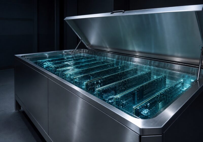
View range 01Single-phase dielectric baths that submerge the whole board, eliminating every server fan and delivering the highest heat capture ratio available.
View range 02Heat rejection plant, thermal instrumentation and leak detection that keep the loop observable, safe and free-cooling for as much of the year…
View range 02Manifolds and blind-mate quick disconnects that split rack flow across every chassis and let a server be pulled under pressure without draining…
View range 02Passive and fan-assisted door coils that neutralise rack exhaust at the boundary, lifting a conventional air-cooled cabinet well past what containment alone…
View rangeModule 02 — Loop schematic
Select any stage to isolate that leg of the loop. Cold supply runs across the top, warm return along the bottom, and the CDU is the pressure and chemistry break between them.
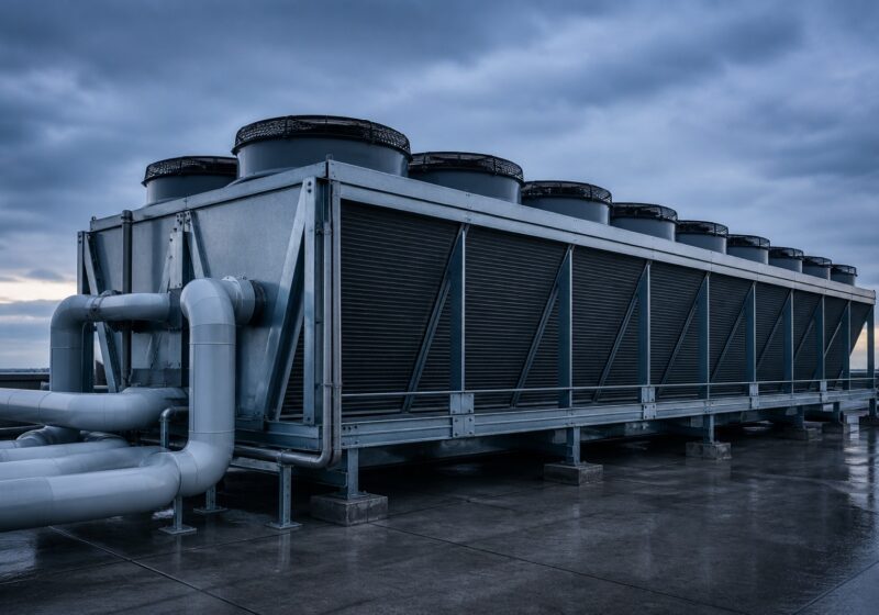
Warm facility water is pushed through a V-bank dry cooler. Above roughly 30 °C supply, free cooling covers the whole year in most temperate climates, and the chiller never starts.
Equipment at this stage
The primary loop carries treated water at ASHRAE W30 to W45. It never touches the servers: the CDU isolates it, so any particulate or chemistry problem stays on the building side of the heat exchanger.
The CDU transfers heat between the two loops, holds secondary supply temperature to ±0.5 K, and keeps the technology loop below the pressure the cold plates are rated for. Redundant pumps carry the load N+1.
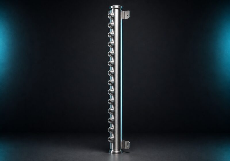
A vertical manifold splits the rack flow across every chassis. Blind-mate quick disconnects let a server be pulled under pressure with a spill measured in droplets, not litres.
A microchannel cold plate sits on the package. Capturing heat at the source is what removes it from the air path entirely — a well-plumbed rack sends 75–95 % of its heat to water and leaves almost nothing for the CRAH.
Selected hardware
Every unit is wet-tested at rated flow before it leaves the floor, and arrives with its own commissioning record.
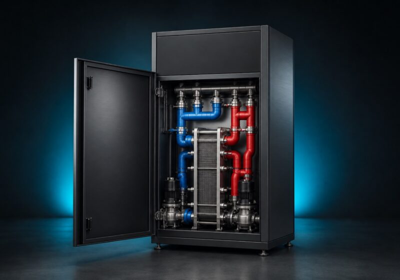
KX-CDU L1300
Our largest floor-standing CDU: 1,300 kW of isolated heat transfer with N+1 pumps and ±0.5 K secondary control.
KX-CDU L600
600 kW in a single-row footprint — the right size for a first liquid cooling pod without over-buying capacity.
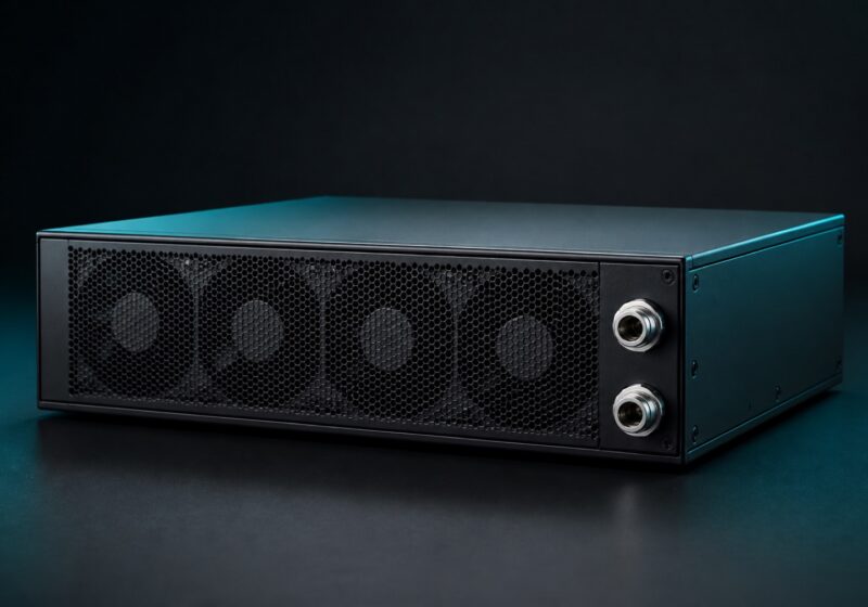
KX-CDU A120
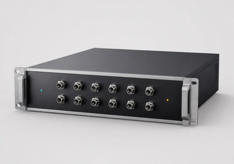
A self-contained 4U CDU that rejects to room air — liquid cooling for sites with no facility water at all.
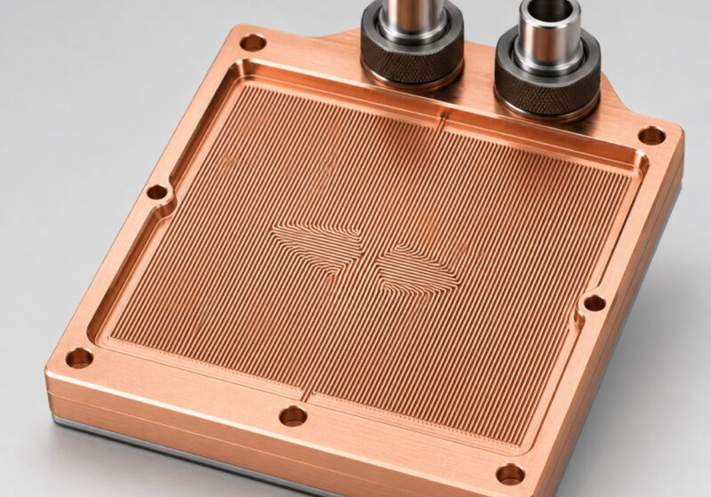
KX-PLATE GX1600
A skived copper microchannel plate rated to 1,600 W per package at a thermal resistance of 0.015 K/W.
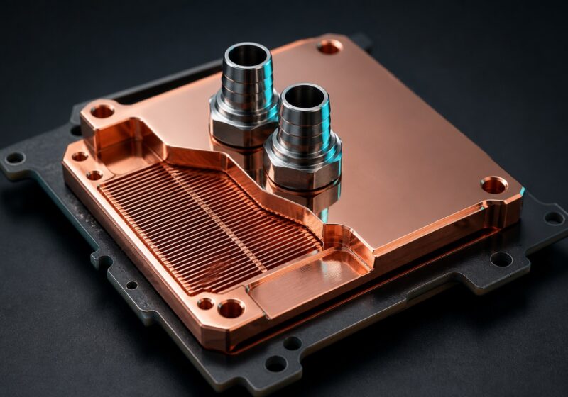
KX-PLATE CX500
A low-profile CPU plate for dense 1U nodes, rated to 500 W with a 0.021 K/W resistance.
KX-MANIFOLD V42
A 42 U stainless supply-and-return pair that splits rack flow across 24 chassis without a single threaded joint inside the cabinet.
Module 03 — Selection wizard
Per-rack power is the single number that decides which cooling path is viable. Move the slider and the recommendation, the expected partial PUE and the matching hardware all follow.
Kilowatts drawn by a single rack at full utilisation.
Profile adjusts the heat-capture assumption and redundancy advice.
Recommended path
Matching hardware
Flow is computed from Q = ṁ × cp × ΔT at a 10 K Delta-T with water at 4.18 kJ/kg·K. Send us the real rack elevation and we will size it properly.
Module 04 — Energy model
Cooling is the second-largest line on a data centre power bill and the only one you can engineer away. Set your own numbers — nothing is sent anywhere, the model runs in your browser.
Annual electricity saved
1,842,000
15,350,000 kWh removed from the cooling overhead every year
Figures are indicative and assume 8,760 operating hours, water at 4.18 kJ/kg·K and a 10 K Delta-T across the loop. Currency is unscaled — read it in whichever unit you entered the price.
Have an engineer verify these numbers
Engineering & support
Kelvinix ships loops, not boxes. Our applications team models the flow network before anything is quoted, and our field engineers stay on the commissioning until the Delta-T on the trend chart matches the one on the drawing.
CFD and hydraulic simulation of the full rack elevation, returned with a sized flow and pressure budget.
Every CDU runs at rated flow and pressure on our test rig; you get the curve, not a claim.
On-site fill, purge, leak-check and control tuning, with a signed acceptance record.
Coolant chemistry, sampling schedule and filtration service for the life of the loop.
How a project runs
A typical retrofit runs sixteen to twenty-two weeks. New build schedules are set by the mechanical contractor, and we work to theirs.
Rack elevations, per-device power, available facility water and the return temperature you need.
Flow network, pressure drop, Delta-T budget and CDU redundancy, issued as a schematic and BOM.
Manufacture, wet test at rated duty, and a witnessed factory acceptance test if you want one.
Mechanical tie-in, flush, fill with treated coolant, pressure hold and leak verification.
Control tuning, trend capture against design, operator training and the maintenance schedule.
Insights
Working papers on density, water temperature and heat capture — written by the people who size the loops.
Air carries roughly 3,000 times less heat per unit volume than water. Here is what that ratio actually does to a rack as the…
Read articleSupply water temperature is the single variable with the largest effect on annual cooling cost — and raising it is usually cheaper than any…
Read articleThe honest comparison is not which technology is more advanced. It is what fraction of rack heat each one removes from the air, and…
Read articleOur applications engineers return a sized loop schematic, flow and Delta-T budget, and a bill of materials within two working days.
Tell us the rack count, per-rack power and the facility water you have available. We reply with a sized solution rather than a brochure.