






How it is built
Four gates between the order and the crate
Select
You send flow, head, fluid, temperature, solids and the NPSH available at the suction flange. We place the duty point on the published curve and tell you where it sits relative to the best-efficiency point — including when the honest answer is a different pump.
Cast and machine
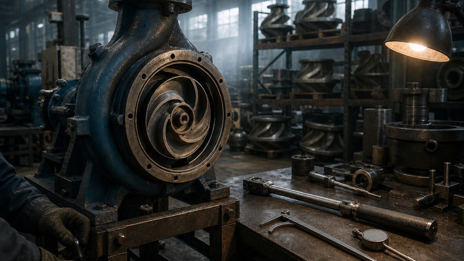
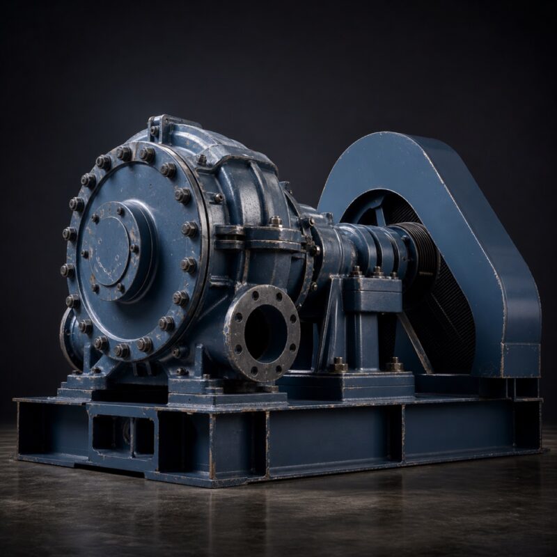
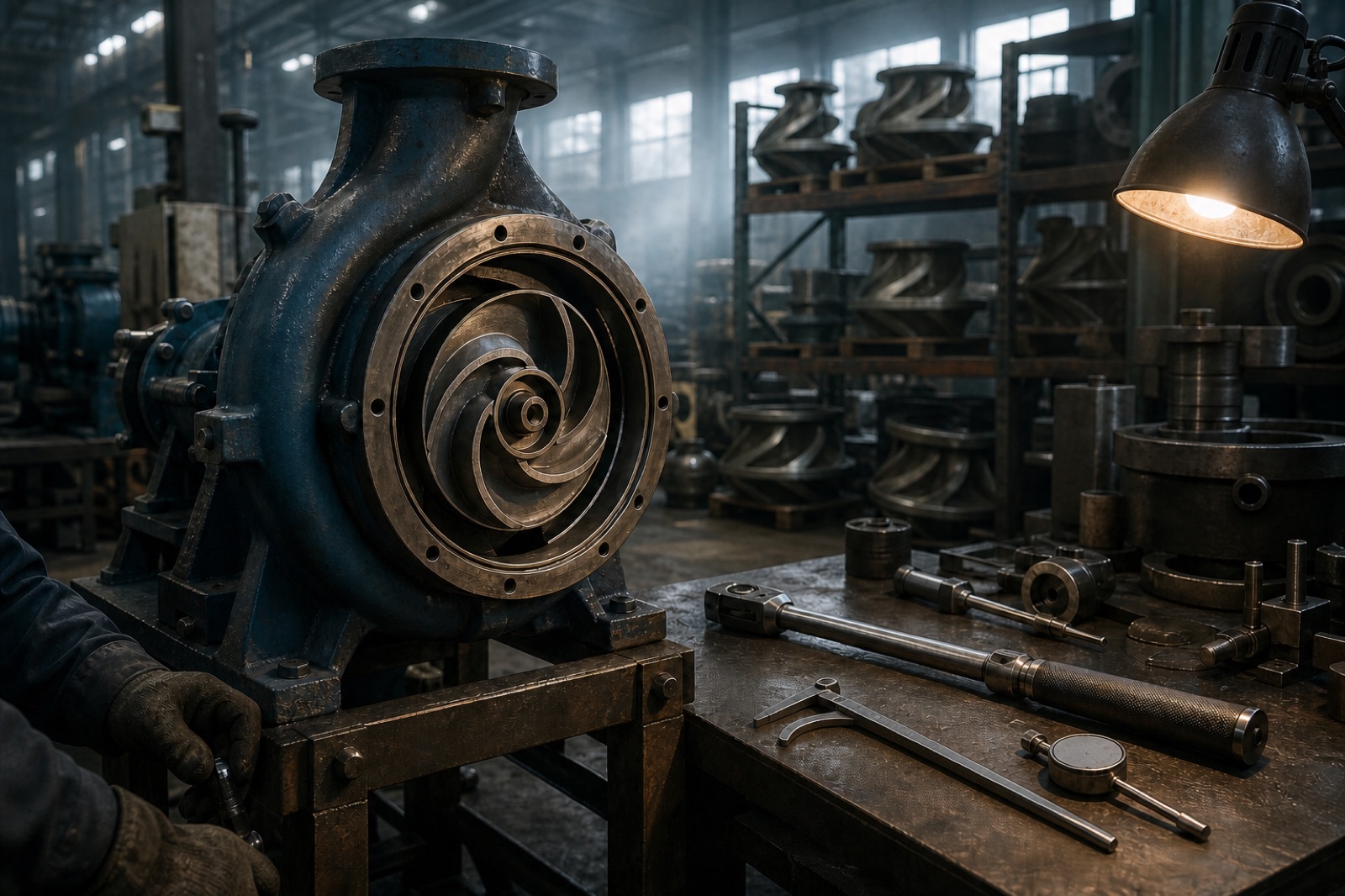
Casings are poured to the material the fluid requires: grey iron for clean water, duplex or CD4MCu for seawater and chlorides, high-chrome for abrasive slurry. Wear rings, shaft sleeves and impeller clearances are machined to the drawing, not to a tolerance band.
Balance and assemble
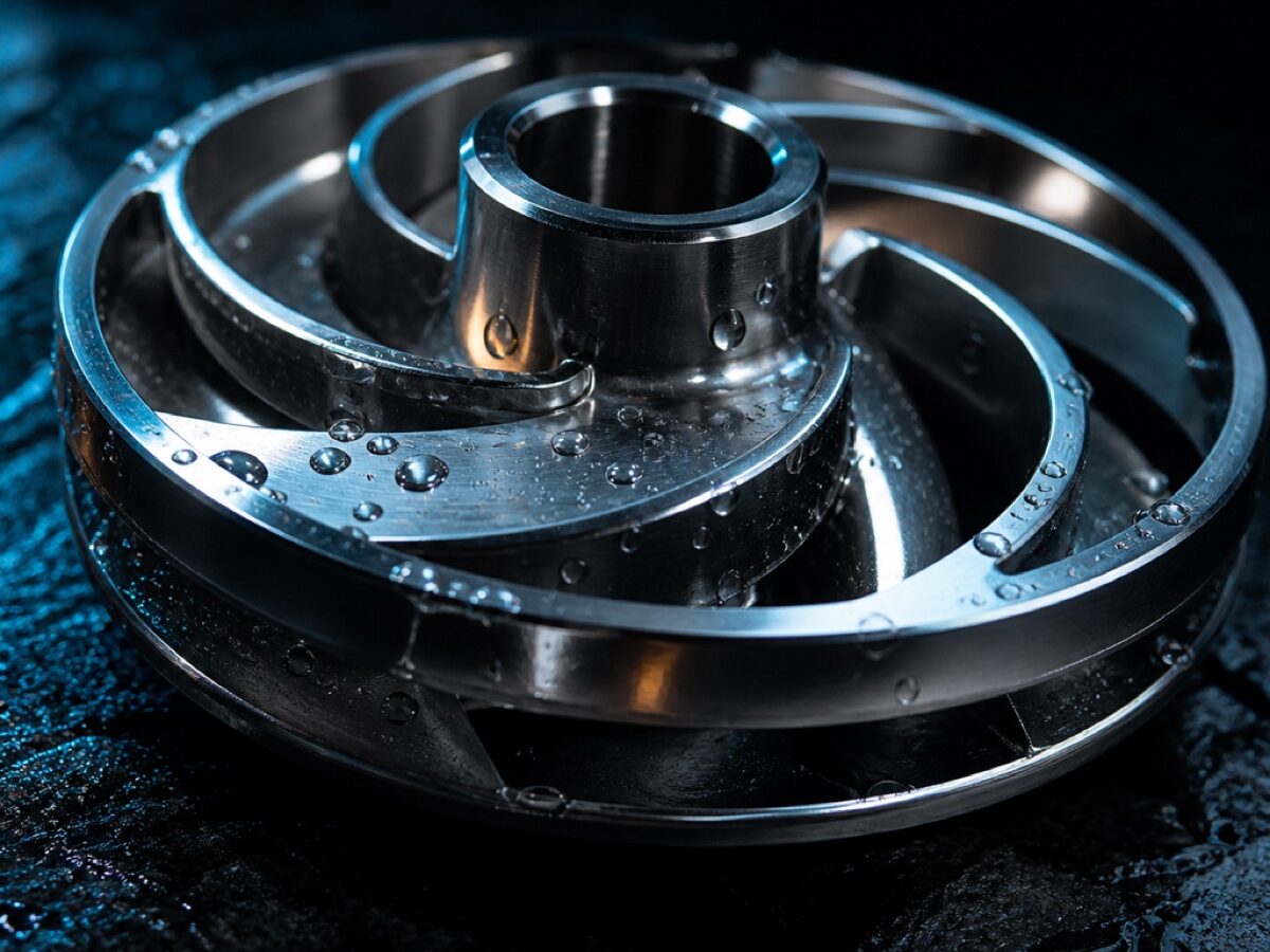
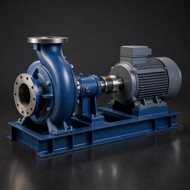
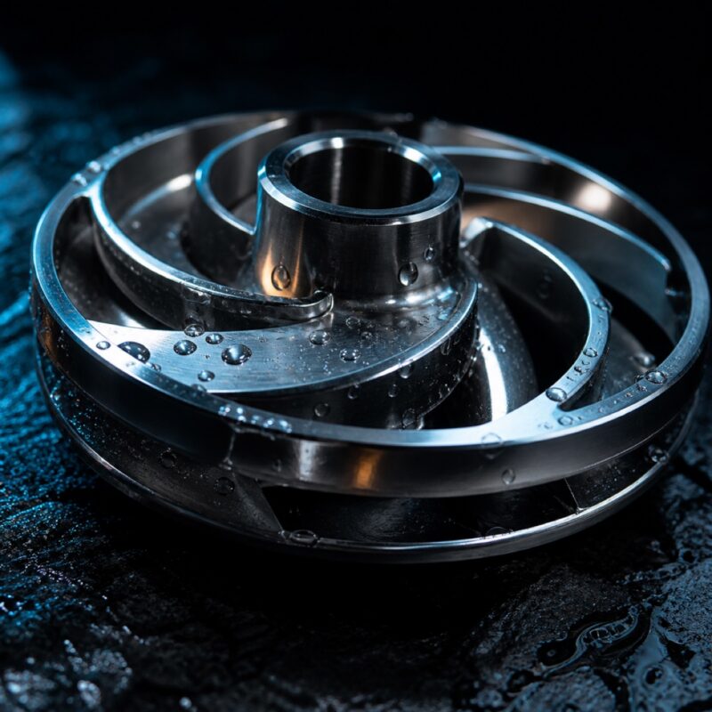
Every impeller is dynamically balanced to ISO 1940 G6.3 before it goes near a shaft. Bearing housings are assembled clean, seals are set to the chosen API 682 plan, and the coupling is laser aligned on the baseplate.
Test and record
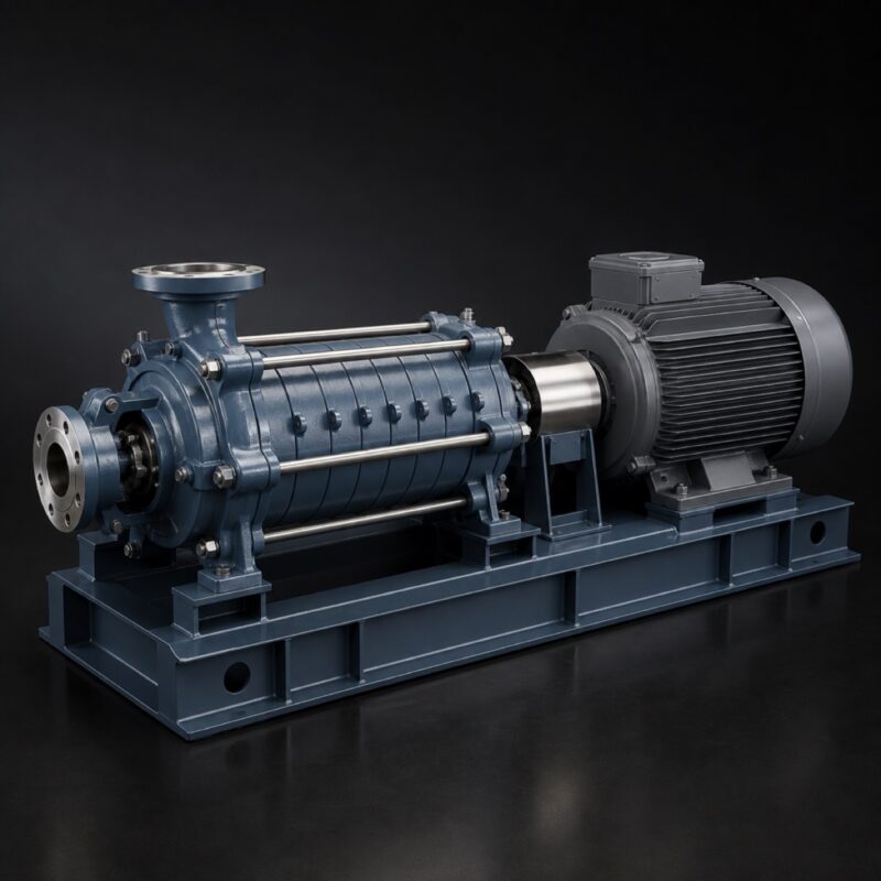
Each unit runs on a hydraulic test rig to ISO 9906 Grade 2. Flow, head, power and vibration are measured across the curve and recorded against the serial number, so the sheet in the crate describes that pump and not the model.